The Goal
Ambient lighting (you may know it as bias lighting, or by Philips’ “Ambilight” brand) puts an LED strip around the back of the TV and lights it to match the edges of whatever is on screen: a forest scene spills green onto the wall behind the panel, an explosion throws orange. Beyond looking good, a lit wall behind the TV reduces eye strain in a dark room and makes the picture feel larger than the panel.
HyperHDR (by awawa-dev, a fork of the original Hyperion) is the software that makes this work. It captures the HDMI signal going to the TV, averages the colors near each edge of the frame, and streams a per-LED color to a small microcontroller that drives the strip. The “HDR” in the name is the point: it handles HDR and Dolby Vision sources properly instead of washing them out, which is the part cheaper kits get wrong.
This note walks through how my rig is wired and configured, with an emphasis on the decisions that are not obvious from the HyperHDR UI: why the capture runs in 10-bit P010, how HDR tone mapping is switched per source, and the level shifter the LED strip needs. It is not a click-by-click build guide, but anyone running HyperHDR should be able to map it onto their own hardware.
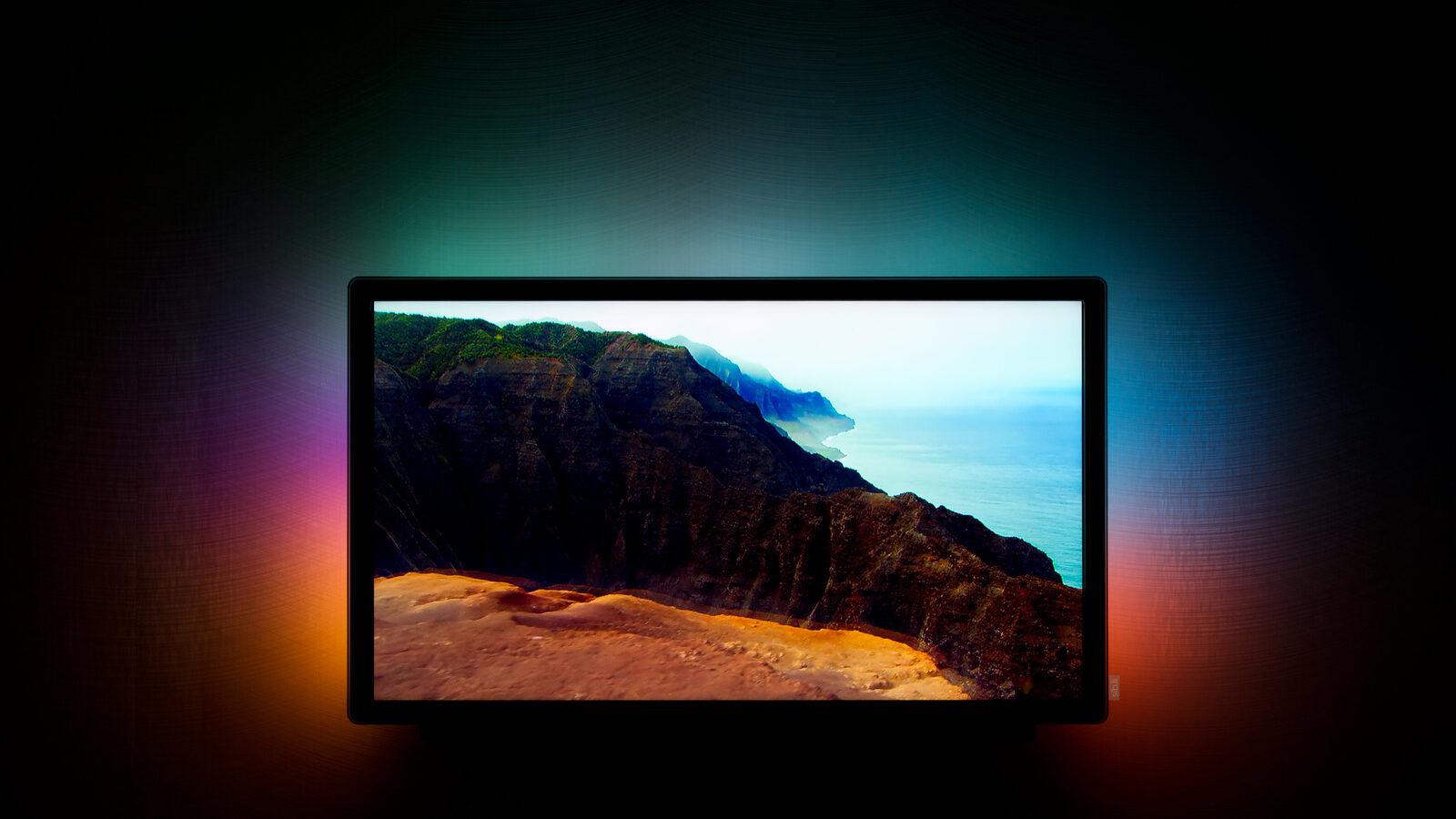 Ambient (bias) lighting in action - illustration. Photo by Stephan Legachev, CC BY 3.0, via Wikimedia Commons.

Signal Chain
Two HDMI sources feed the TV, and the whole job of the wiring is to mirror that exact feed into a capture card without disturbing what reaches the screen.
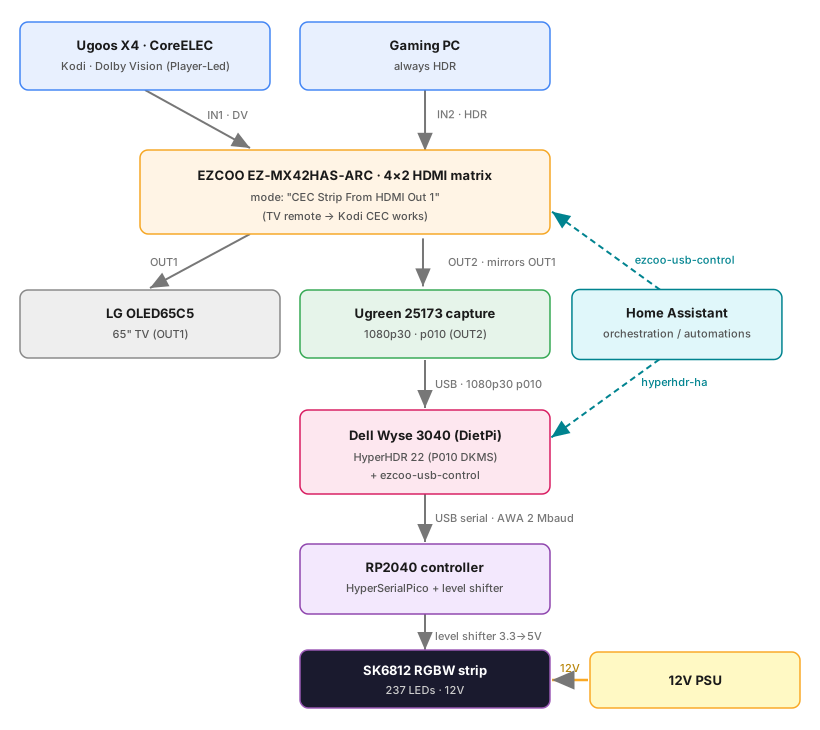
- Sources into the EZCOO matrix:
- IN1 - Ugoos X4 running CoreELEC (Kodi, Dolby Vision)
- IN2 - the gaming PC from the Linux Multi-Seat Gaming series
- Matrix outputs:
- OUT1 - the LG OLED (the actual TV)
- OUT2 - locked to mirror OUT1 into the Ugreen capture card, so HyperHDR always sees exactly what is on the TV
- Host: the capture card feeds the HyperHDR host over USB; HyperHDR samples the frame edges and streams per-LED colors over USB serial to the RP2040 controller, which drives the SK6812 strip through a level shifter.
- Orchestration: Home Assistant flips the matrix inputs (via
ezcoo-usb-control) and toggles HyperHDR state (via thehyperhdr-haintegration). - Power: the strip runs off a separate 12 V supply.
The matrix runs in its “CEC Strip From HDMI Out 1” mode so HDMI-CEC still passes between the TV and CoreELEC, letting the TV remote drive Kodi; see the EZCOO entry below.
Hardware
Host. The simplest, recommended platform is a Raspberry Pi 4: HyperHDR ships a
ready-made Pi image with the 10-bit p010 capture patch already built in, so it works out
of the box. Mine started there. The Pi 4 later died, and the current host is a Dell Wyse
3040 thin client (Intel Atom x5-Z8350, 2 GB RAM, 8 GB eMMC) running DietPi - a cheap,
fanless x86 box. Moving to x86 loses the pre-patched image; that, and the OS rebuild, are
covered under Migrating to an x86 host below.
Ugreen 25173 capture card. A USB capture stick the HyperHDR maintainer
recommends for its P010 support,
which is why I picked it. Configured for 1080p @ 30 fps in 10-bit p010 format;
the matrix mirrors the TV feed into it so HyperHDR always sees the live picture. Why P010
rather than plain 8-bit is its own topic - see
10-bit P010 capture.
A 1080p P010 frame is uncompressed and large - roughly 185 MB/s at 30 fps (24 bits/pixel for 4:2:0 10-bit), well past anything USB 2.0 could carry, so the card needs a real USB 3.0 port. HyperHDR’s 25% downscale happens later, in software on the host, not on the wire.
EZCOO EZ-MX42HAS-ARC HDMI matrix (4×2). A plain HDMI splitter would have been enough to mirror one source to both the TV and the capture card. But I have two sources (the Ugoos and the gaming PC) and want to switch between them, which a splitter cannot do. A matrix both switches inputs and feeds two outputs, so it handles switching and mirroring in one box. Only two inputs and both outputs are used:
- IN1 - Ugoos X4 / CoreELEC, Dolby Vision in Player-Led mode
- IN2 - gaming PC, permanently in HDR
- OUT1 - LG OLED65C5 (the TV)
- OUT2 - Ugreen capture card, locked to mirror OUT1
- Mode - “CEC Strip From HDMI Out 1”, which keeps TV-remote → Kodi CEC working
It is driven over USB serial by a small utility I wrote; see
ezcoo-usb-control under Software.
RP2040 LED controller (DIY). A homemade board around a Raspberry Pi Pico (RP2040) that takes the serial stream from HyperHDR and drives the strip, running the HyperHDR project’s HyperSerialPico firmware. The Pico’s 3.3 V data line cannot reliably drive a 5 V LED strip on its own, so the board includes a level shifter - see The level shifter for why and how.
LED strip. BTF-Lighting DC12V SK6812 RGBW (RGB + CW), 60 LEDs/m, 5 m.
Corner guides. To avoid cutting and re-soldering the strip at the TV corners, I printed these LED-strip corner guides on the 3D printer.
Power. A generic 12 V PSU that was already on hand.
Software
Beyond HyperHDR itself, a few pieces make the system behave:
ezcoo-usb-control - my
own service. It runs on the HyperHDR host, talks to the EZCOO matrix over USB serial on
/dev/ttyUSB0, and exposes it to Home Assistant via MQTT discovery, so HA can switch
inputs and read the matrix state. Note /dev/ttyUSB0 is a different device from the Pico
LED controller, which enumerates as /dev/ttyACM0 over USB CDC - two USB-serial endpoints
on one host, easy to mix up.
service.video.hdrnotify -
a Kodi service add-on I wrote. On playback start it reads Kodi’s VideoPlayer.HdrType
infolabel and calls HyperHDR’s videomodehdr JSON-RPC command, so tone mapping follows the
actual HDR type of the video (hdr10 / dolbyvision / hlg) rather than relying on
HyperHDR’s own signal auto-detection, which is unreliable on this setup. See
HDR tone-mapping control for how it fits with the Home
Assistant automation.
hyperhdr-ha - the Home Assistant integration for HyperHDR. The automations below drive HyperHDR through this integration rather than poking its REST API by hand.
Home Assistant automations (three):
- EZCOO HDMI Matrix - sync outputs - keeps the capture-card output (OUT2) locked to whatever is going to the TV (OUT1), so HyperHDR always sees the on-screen picture.
- Sync HyperHDR HDR Tone Mapping with EZCOO input - enables HDR tone mapping when EZCOO Output 1 = IN2, disables it when Output 1 = IN1. IN2 is the gaming PC, which is always in HDR.
- Sync HyperHDR LED with LG TV power - enables/disables the first LED instance
(component
ALL) in sync with the LG webOS TV power state. Turn the TV off and the backlight goes dark with it.
What’s specific to this setup
A stock HyperHDR install on the supported Raspberry Pi image gets you most of the way. The parts below are where my rig diverges from that default - the decisions worth understanding if you are copying any of it.
10-bit P010 capture and the 4K matrix
The capture format is raw P010 rather than the usual 8-bit. P010 hands HyperHDR a raw 10-bit frame instead of one the grabber has already “improved” by treating HDR as SDR - that kind of pre-processing is what people report wrecking color accuracy on cheaper 8-bit grabbers. It comes with two requirements, both reflected in the capture settings: the grabber needs the official P010 LUT (HyperHDR’s default LUT does not decode P010), and “Quarter of frame” scaling is recommended and left on.
The matrix side matters too. The EZCOO can downscale 4K → 1080p on its output, and the two outputs can run at different resolutions at once. I deliberately do not use that: the EZCOO is an 8-bit HDR device, so putting its scaler in the capture path risks handing the card an 8-bit, tone-mapped 1080p signal instead of raw 10-bit. Letting the matrix pass 4K untouched and having the capture card produce the 1080p P010 keeps the HDR depth intact. Resolution beyond 1080p buys nothing for ambient light anyway; it only costs CPU.
HDR tone-mapping control
Two layers decide when HyperHDR applies HDR tone mapping. They deliberately work at different granularities, on different triggers, so they never both decide at once.
The coarse layer is the Home Assistant automation, keyed to the EZCOO input. Switching to IN2 (gaming PC) forces tone mapping on - that machine is always in HDR. Switching to IN1 (Ugoos) forces tone mapping off, because the Kodi UI itself is SDR. This only fires at the moment the matrix input changes.
The fine layer is the Kodi add-on, and it is only relevant on the Ugoos. When a video
starts, service.video.hdrnotify reads its HDR type and tells HyperHDR directly whether to
tone-map - on for an HDR/Dolby Vision title, off for an SDR one - then resets to SDR when
playback stops.
So when an HDR movie plays on the Ugoos, it is the add-on, not Home Assistant, that turns tone mapping on: the input never changed when the movie started, so the HA automation has no trigger and never re-runs. It only set the SDR baseline earlier, for the Kodi menu.
The add-on can actually drive two independent targets: it can POST straight to HyperHDR’s JSON-RPC (what I use), or fire a Home Assistant webhook carrying the HDR state. The webhook route would let an HA automation own the toggle and keep all the lighting logic in one place. I went with the direct path because it is simpler and works; the webhook stays available if I ever want to consolidate everything into Home Assistant.
The level shifter
The Pico’s data line swings to 3.3 V, but the strip wants a ~5 V logic high, so the raw
signal is marginal - it works until it doesn’t, depending on strip length, temperature and
the first LED’s input threshold. HyperHDR’s docs recommend a 74AHCT125 buffer to fix
this; powered from 5 V, it re-levels the Pico’s 3.3 V data to a solid 5 V swing. Only one
of the chip’s four buffers is used: data in on 1A (pin 2), data out on 1Y (pin 3),
output-enable 1OE (pin 1) tied to ground (it is active-low), VCC (pin 14) and GND
(pin 7) to 5 V and ground. The strip’s 12 V comes from a separate supply, and everything
shares a common ground.
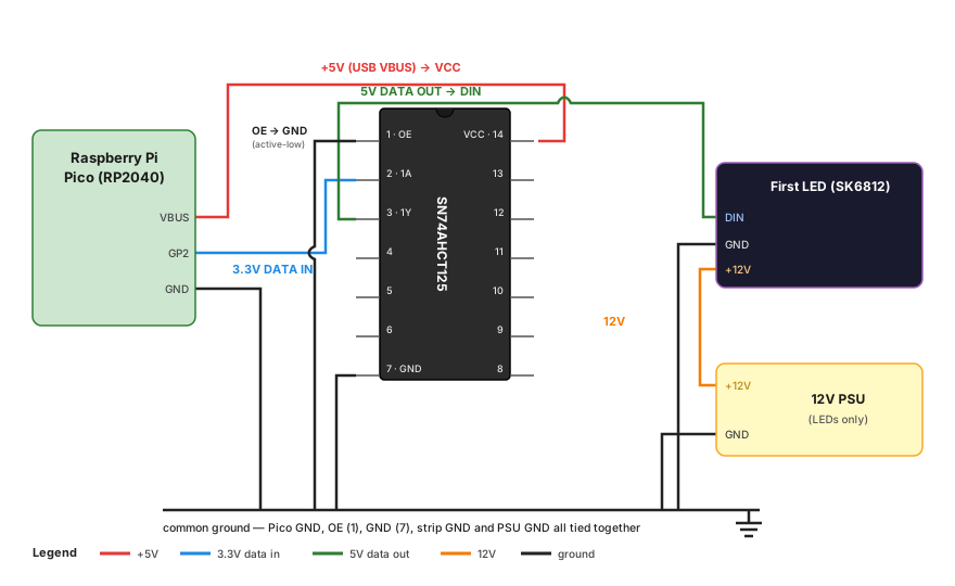
The HyperSerialPico README also lists ready-made boards with the level shifter already integrated. I would happily have bought one, but couldn’t find any at a sensible price, so I soldered a 74AHCT125 onto protoboard next to a Pico myself.
Migrating to an x86 host
The Raspberry Pi 4 that originally ran this died. Rather than buy another Pi, I moved to a
Dell Wyse 3040 - fanless, x86, and cheap secondhand. The catch is that x86 has no
pre-patched HyperHDR image, so the p010 V4L2 support has to be built as a DKMS kernel
module (P010_for_V4L2) instead of coming
ready in the image - that is what makes the Ugreen card’s p010 format visible to V4L2.
The full OS rebuild (flashing DietPi, the DKMS build, getting capture working again) is its
own write-up.
Current HyperHDR Configuration
Running HyperHDR 22.0.0.0beta2 on Linux (V4L2). A single instance (“First LED instance”). The values below are the current snapshot; anything not called out is left at HyperHDR’s default.
Video capturing
- Device: Ugreen 25173, Input: Automatic
- Resolution: 1920×1080, 30 fps, format
p010 - LUT: the official LUT for this grabber, downloaded directly from the HyperHDR web UI (P010 will not work with the default LUT)
- Scale frame size to 25%: on (this is the “Quarter of frame” mode HyperHDR recommends for P010)
- HDR → SDR tone mapping: off at the grabber (toggled at runtime - see HDR tone-mapping control)
- Software frame skipping: 1 (every frame is processed; higher values decimate the capture to save CPU)
- Auto resume: on; automatic/manual signal detection: off
- Priority channel: 240 (default)
LED hardware (controller)
- Controller type:
adalight, outputttyACM0 - High-speed serial AWA protocol with data integrity check: on
- Baudrate: 2,000,000 (the HyperSerialPico default)
- ESP8266/ESP32/RP2040/RP235x handshake: on
- RGBW with dithering (Infinite Color Engine): on; white intensity 1.8, temperature neutral
LED layout
- Top 84, Bottom 84, Left 46, Right 46
- Gap length 23 at the bottom center (TV stand), gap/input position 159
- Total: 237 LEDs (260 positions around the frame minus the 23-LED gap at the bottom)
HyperHDR indexes every position around the frame in one continuous count. Input position is the index of the first physical LED (where the Pico’s data line enters the strip) and gap position is where the unlit gap begins; both are 159 here, which puts the feed point and the gap together at the bottom centre, behind the TV stand. The exact number depends on which corner HyperHDR starts from and the walk direction, so if you ever re-glue the strip, set these from where your data actually enters rather than copying 159.
Image processing
- LED area assignment: Multicolor (precise average per LED)
- Smoothing: Infinite Interpolator (hybrid physics), time 150 ms, update 50 Hz, stiffness 150, damping 26, anti-flicker on - all left at the mode’s defaults
What Works
The whole chain has been stable in daily use for me - with the caveat that this is
HyperHDR 22.0.0.0beta2 on an out-of-tree DKMS module and DIY hardware, so read the
specifics as “works on my setup”, not guarantees. It also survived its biggest change
intact: moving off the dead Raspberry Pi 4 onto the custom x86 Wyse host. The p010
capture that came pre-built on HyperHDR’s Pi image now runs from a hand-built DKMS module,
and nothing downstream - LED layout, tone-mapping logic, automations - noticed the swap.
With a movie playing, the capture runs the full ~30 fps end to end through to the LEDs. CEC from the TV remote reaches Kodi on the
Ugoos through the matrix. HDR tone mapping flips with the content through both control
paths, so the LED colors track HDR game content and HDR/SDR playback on the Ugoos
correctly. The strip follows TV power - turn the OLED off and the backlight goes with it,
no stray glow. The RP2040 + HyperSerialPico link runs the AWA protocol at 2 Mbaud with the
integrity check on and hasn’t given me trouble so far.
Caveats / Open Items
Input switching on the matrix still has no convenient trigger. Right now I open the Home Assistant dashboard and pick the source from a dropdown there. It works, but it is the one part of the flow that isn’t automatic or tied to a physical control - everything else runs hands-off.
The other thing to keep an eye on is the capture stack itself: beta HyperHDR plus the out-of-tree P010 DKMS module. That combination is the most likely source of a future quiet breakage (for example after a kernel upgrade) - the rebuild note covers how the DKMS module is built and what keeps it rebuilding.